このドキュメントは http://edu.net.c.dendai.ac.jp/ 上で公開されています。
本日はグループワークはありません。授業の感想をTDUitterに投稿して 下さい。
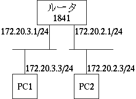
20世紀のインターネットは、これまでやってきたように、ローカルネットワー ク同士がルータにより接続されてきました。
ルータには接続用のポートがあり、それぞれが別のローカルネットワークに接 続して、ローカルネットワーク同士を接続していました。 これは、各ローカルネットワークの設置場所にルータが必要で、さらに、離 れた場所のローカルネットワークを接続する場合、その間を結ぶ回線が必要で、 その回線も別のネットワークとして扱う必要がありました。 この頃の構内ネットワーク(キャンパスネットワークなど)は、バックボーン と支線とをルータで結ぶ構造が一般的でした。
20世紀の終わり頃にEthernet のスイッチングハブとVLANが普及しました。 従来のハブ(リピータハブ)はハブの中で信号を転送、共有することで、通 信線を集約していました。この場合、ハブの中は高々一つの信号が送受され るため、台数が多くなるほど効率は悪くなり、また半二重通信(送信と受信は同時にできない)でした。またハブを数珠つなぎにする段数に制限がありました。 しかし、スイッチングハブは集約した通信線を交換技術により接続すること で、混信が起こりにくく、全二重通信(送信と受信を同時にできる)を実現 しました。 さらに、スイッチングは転送ではないので、転送段数制限は無くなりました。
VLAN は、従来のEthernet を拡張したもので、VLAN ID という番号が導入さ れました。 これにより、Ethernet によるローカルネットワークは、それぞれに VLAN ID を持ち、各パケットもVLAN IDを持つため、パケットは混ざっていても、き ちんと所属 VLAN に転送されるようになりました。 これにより、すべてのローカルネットワークは単純に VLAN 対応のハブに接 続すればよく、個々にVLAN ID を与えれば良いことになります。 そして、どこか一箇所ですべてのVLAN に接続するルータを設置すれば、組 織内のすべてのローカルネットワークが行えるようになります。 このように一つのルータにすべてのローカルネットワークが(仮想的に)集 約されるネットワークをスター型ネットワークといいます。 このようなVLAN対応のルータは多くのローカルネットワークをVLANとして集約 するため、形状としてもスイッチングハブと同様の多くのEthernet と接続 できるようにコネクタが用意されています。 そのため、ルーティング機能のある交換機という意味で、ルータとは呼ばず、 レイヤ3スイッチと呼びます。
次のような、二つのネットワークを一台のルータで接続した単純なネットワー クを構築する実験を行います。
但し、これを実現するのに、ルータ一台の他、スイッチ一台、パソコン一台だ けを使用します。 そのため、VLAN、 Virtual Machine を活用します。
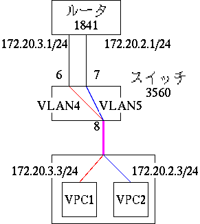
まず、ルータ、スイッチ、PC を接続します。 ルータの FastEthernet0/0 をスイッチの FastEthernet0/6 に、 ルータの FastEthernet0/1 をスイッチの FastEthernet0/7 につなぎます。 PC をスイッチの FastEthernet0/8 につなぎます。 なお、アドレスを設定せずにルータ、スイッチを輪になるように接続すると、 802.1d のプロトコルにより、輪ができている状態を解消するために、一部のポート が停止します。 これは、アドレスを振りなおした後でポートを起動すれば使用できるようにな りますので、問題ありません。
また、ルータやスイッチを接続するためのシリアルケーブルを PC に接続しま す。 PC では Tera Term などの端末ソフトを起動します。
Intel の最近のネットワーク用の IC にはノートパソコンに搭載されているも のでも VLAN 機能を持っています。 但し、 Windows に最初から搭載されているドライバーにはその機能がありま せんので、ドライバーをインストールする必要があります。 それは、Advanced Network Services という機能です。 http://downloadcenter.intel.com/Default.aspx?lang=jpn にアクセスし、 ネットワークアダプタと OS を選択して、 Advaneced Network Services が搭 載されているドライバーをインストールします。
これにより、ネットワークアダプタの「構成」ボタンにおいて、 VLAN タブが 有効になります。
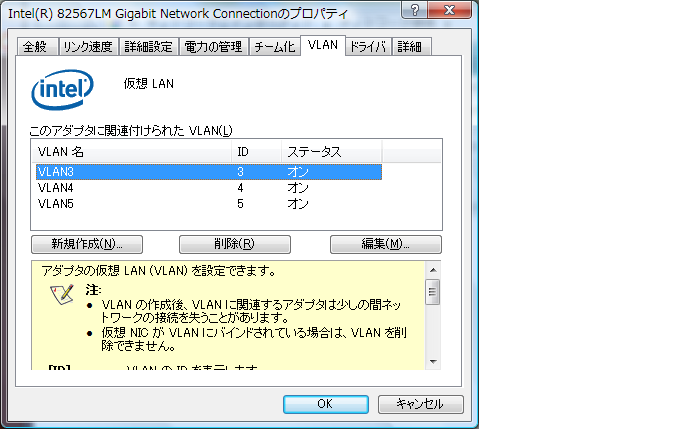
ここでは VLAN14 と VLAN15 を作成しておきます。 作成すると、 Windows にネットワークデバイスとして追加されます。 一方で、従来のネットワーク接続は失われますので注意が必要です。

VLAN14 には 172.20.13.2/24, VLAN15 には 172.20.12.2/24 を設定します。
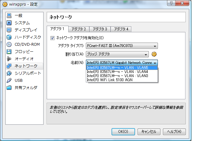
無料で Windows OS も動作する、Sun の Virtual Box を利用しました。 Windows XP に近いOSとして ReactOS を 2 つ用意します。 それぞれ winxp1 と winxp2 と名前を付けます。
ネットワークは「ブリッジ接続」を選び、 winxp1 は VLAN14 のインターフェ イスに、 winxp2 は VLAN15 のインターフェイスに接続します。 そして、 winxp1 の IP アドレスを 172.20.13.3/24 に、デフォルトゲートウェイ を 172.20.13.1 に、 winxp2 の IP アドレスを 172.20.12.3/24 に、デフォル トゲートウェイを 172.20.12.1 に設定します。
VLAN を使用するため、 802.1Q という規格を使います。 CISCO では、複数の VLAN を一本の線に乗せることをtrunkと呼ん でいます。 一方、他社では違う呼び方をしています。 802.1Q という規格では、複数の VLAN パケットを混ぜる際に、個々の識別の ために Ether パケットのフレームを拡張して VLAN 番号でタグ付けをします。 そのため、802.1Q の規格による VLAN を タグ付き VLAN と呼んだり、混ぜて送受するポートを タグ付きポート と呼んだりします。
設定はポート 6 が VLAN14, ポート 7 を VLAN15 とします。 そして、ポート 8 は dot1q 指定の trunc に指定し、VLAN14 と VLAN15 を通 します。
configure terminal

vlan 14
exit

vlan 15
exit

interface fastethernet0/6
switchport mode access
switchport access vlan 14
exit

interface fastethernet0/7
switchport mode access
switchport access vlan 15
exit

interface fastethernet0/8
switchport trunk encapsulation dot1q
switchport mode trunk
switchport trunk allowed vlan 14,15
end
スイッチの設定の確認は show vlan、show interfaces FastEthernet0/8 switchport などで確認します。
catalyst3560#show vlan

VLAN Name                             Status    Ports
---- -------------------------------- --------- -------------------------------
1    default                          active    Fa0/1, Fa0/2, Fa0/3, Fa0/4
                                                Fa0/5, Gi0/1
4    VLAN0014                         active    Fa0/6
5    VLAN0015                         active    Fa0/7
1002 fddi-default                     act/unsup
1003 token-ring-default               act/unsup
1004 fddinet-default                  act/unsup
1005 trnet-default                    act/unsup

VLAN Type  SAID       MTU   Parent RingNo BridgeNo Stp  BrdgMode Trans1 Trans2
---- ----- ---------- ----- ------ ------ -------- ---- -------- ------ ------
1    enet  100001     1500  -      -      -        -    -        0      0
14    enet  100004     1500  -      -      -        -    -        0      0
15    enet  100005     1500  -      -      -        -    -        0      0
1002 fddi  101002     1500  -      -      -        -    -        0      0
1003 tr    101003     1500  -      -      -        -    -        0      0
1004 fdnet 101004     1500  -      -      -        ieee -        0      0
1005 trnet 101005     1500  -      -      -        ibm  -        0      0

Remote SPAN VLANs
------------------------------------------------------------------------------


Primary Secondary Type              Ports
------- --------- ----------------- ------------------------------------------
catalyst3560#show interface FastEthernet 0/8 switchport
Name: Fa0/8
Switchport: Enabled
Administrative Mode: trunk
Operational Mode: trunk
Administrative Trunking Encapsulation: dot1q
Operational Trunking Encapsulation: dot1q
Negotiation of Trunking: On
Access Mode VLAN: 1 (default)
Trunking Native Mode VLAN: 3 (VLAN0003)
Administrative Native VLAN tagging: enabled
Voice VLAN: none
Administrative private-vlan host-association: none
Administrative private-vlan mapping: none
Administrative private-vlan trunk native VLAN: none
Administrative private-vlan trunk Native VLAN tagging: enabled
Administrative private-vlan trunk encapsulation: dot1q
Administrative private-vlan trunk normal VLANs: none
Administrative private-vlan trunk private VLANs: none
Operational private-vlan: none
Trunking VLANs Enabled: 14,15
Pruning VLANs Enabled: 2-1001
Capture Mode Disabled
Capture VLANs Allowed: ALL

Protected: false
Unknown unicast blocked: disabled
Unknown multicast blocked: disabled
Appliance trust: none
この実験ではルータのフォワーディング機能を確認します。
configure terminal
interface FastEthernet0/0
ip address 172.20.13.1 255.255.255.0
no shutdown
exit
interface FastEthernet0/1
ip address 172.20.12.1 255.255.255.0
no shutdown
end
ここで、 no shutdown を指定しないと、接続時に停止したポートが有効にな りませんので注意が必要です。
設定を確認するには、 show ip route を打つことで、自動的にルー ティングテーブルに接続したポートが自動的に追加されていることが確認でき ます。
Router# show ip route
Codes: C - connected, S - static, R - RIP, M - mobile, B - BGP
       D - EIGRP, EX - EIGRP external, O - OSPF, IA - OSPF inter area
       N1 - OSPF NSSA external type 1, N2 - OSPF NSSA external type 2
       E1 - OSPF external type 1, E2 - OSPF external type 2
       i - IS-IS, su - IS-IS summary, L1 - IS-IS level-1, L2 - IS-IS level-2
       ia - IS-IS inter area, * - candidate default, U - per-user static route
       o - ODR, P - periodic downloaded static route

Gateway of last resort is not set

     172.20.0.0/24 is subnetted, 2 subnets
C       172.20.12.0 is directly connected, FastEthernet0/1
C       172.20.13.0 is directly connected, FastEthernet0/0
このような設定において、 VPC1 から VPC2 へ ping を打つと、返事が返って きます。これは何故でしょう?
VPC1 のルーティングテーブルは次の様になっています。
C:\Documents and Settings\sakamoto>route print
===========================================================================
Interface List
0x1 ........................... MS TCP Loopback interface
0x2 ...08 00 27 25 dd 70 ...... AMD PCNET Family PCI Ethernet Adapter - パケット
 スケジューラ ミニポート
===========================================================================
===========================================================================
Active Routes:
Network Destination        Netmask          Gateway       Interface  Metric
          0.0.0.0          0.0.0.0       172.20.13.1      172.20.13.3       20
        127.0.0.0        255.0.0.0        127.0.0.1       127.0.0.1       1
       172.20.13.0    255.255.255.0       172.20.13.3      172.20.13.3       20
       172.20.13.3  255.255.255.255        127.0.0.1       127.0.0.1       20
   172.20.255.255  255.255.255.255       172.20.13.3      172.20.13.3       20
        224.0.0.0        240.0.0.0       172.20.13.3      172.20.13.3       20
  255.255.255.255  255.255.255.255       172.20.13.3      172.20.13.3       1
Default Gateway:        172.20.13.1
===========================================================================
Persistent Routes:
  None
このうち本質的なのは次です。
Network Destination        Netmask          Gateway       Interface  Metric
          0.0.0.0          0.0.0.0       172.20.13.1      172.20.13.3       20
       172.20.13.0    255.255.255.0       172.20.13.3      172.20.13.3       20
送信元 172.20.13.3、宛先 172.20.12.3 の ICMP エコーパケットがデフォルト ゲートウェイ172.20.13.1 に送られます。
show ip route による出力は次の通りです。
Router# show ip route
Codes: C - connected, S - static, R - RIP, M - mobile, B - BGP
       D - EIGRP, EX - EIGRP external, O - OSPF, IA - OSPF inter area
       N1 - OSPF NSSA external type 1, N2 - OSPF NSSA external type 2
       E1 - OSPF external type 1, E2 - OSPF external type 2
       i - IS-IS, su - IS-IS summary, L1 - IS-IS level-1, L2 - IS-IS level-2
       ia - IS-IS inter area, * - candidate default, U - per-user static route
       o - ODR, P - periodic downloaded static route

Gateway of last resort is not set

     172.20.0.0/24 is subnetted, 2 subnets
C       172.20.12.0 is directly connected, FastEthernet0/1
C       172.20.13.0 is directly connected, FastEthernet0/0
Router#
受け取った 172.20.12.3 宛のパケットに関しては、ルーティングテーブルに当 該ネットワークが存在するので、フォワーディングされます。
ルータより、送信元 172.20.13.3、宛先 172.20.12.3 の ICMP エコーパケット が到達します。
その結果、送信元 172.20.12.3、宛先 172.20.13.3 の ICMP エコーリプライパ ケットが生成されます。 この時、VPC2 のルーティングテーブルは次の様になっています。
C:\Documents and Settings\sakamoto>route print
===========================================================================
Interface List
0x1 ........................... MS TCP Loopback interface
0x2 ...08 00 27 25 dd 70 ...... AMD PCNET Family PCI Ethernet Adapter - パケット
 スケジューラ ミニポート
===========================================================================
===========================================================================
Active Routes:
Network Destination        Netmask          Gateway       Interface  Metric
          0.0.0.0          0.0.0.0       172.20.12.1      172.20.12.3       20
        127.0.0.0        255.0.0.0        127.0.0.1       127.0.0.1       1
       172.20.13.0    255.255.255.0       172.20.12.3      172.20.12.3       20
       172.20.13.3  255.255.255.255        127.0.0.1       127.0.0.1       20
   172.20.1255.255  255.255.255.255       172.20.12.3      172.20.12.3       20
        224.0.0.0        240.0.0.0       172.20.12.3      172.20.12.3       20
  255.255.255.255  255.255.255.255       172.20.12.3      172.20.12.3       1
Default Gateway:        172.20.12.1
===========================================================================
Persistent Routes:
  None
このうち本質的なのは次です。
Network Destination        Netmask          Gateway       Interface  Metric
          0.0.0.0          0.0.0.0       172.20.12.1      172.20.12.3       20
       172.20.12.0    255.255.255.0       172.20.12.3      172.20.12.3       20
これにより、送信元 172.20.12.3、宛先 172.20.13.3 の ICMP エコーリプライ パケットがデフォルトゲートウェイ172.20.12.1 に送られます。
show ip route による出力は先ほど同様に、次の通りです。
     172.20.0.0/24 is subnetted, 2 subnets
C       172.20.12.0 is directly connected, FastEthernet0/1
C       172.20.13.0 is directly connected, FastEthernet0/0
受け取った 172.20.13.3 宛のパケットに関しては、ルーティングテーブルに当 該ネットワークが存在するので、フォワーディングされます。
以上のプロセスにより、 ICMPエコーリプライパケットが返ってきます。
以上のシナリオにおいて、パケットの転送に用いられた情報は以下の通りです。
つまりルータ 1 台のみの状況においては、パソコンでデフォルトゲートウェ イを設定しておけば、ルータでルーティングを特に設定しなくてもパケットの 交換は可能なことがわかります。
次のような、3つのネットワークを2台のルータで接続したネットワー クを構築する実験を行います。
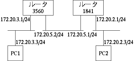
但し、これを実現するのに、ルータ一台の他、スイッチ一台、パソコン一台だ けを使用します。 そのため、実験1同様にVLAN、 Virtual Machine を活用します。
なお、今回はスイッチでもルーティングを行います。 ポートと VLAN 間でルーティングします。
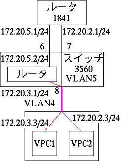
まず、ルータ、スイッチ、PC を接続します。 これは実験1と同様です。 ルータの FastEthernet0/0 をスイッチの FastEthernet0/6 に、 ルータの FastEthernet0/1 をスイッチの FastEthernet0/7 につなぎます。 PC をスイッチの FastEthernet0/8 につなぎます。 なお、アドレスを設定せずにルータ、スイッチを輪になるように接続すると、 802.1d のプロトコルにより、輪ができている状態を解消するために、一部のポート が停止します。 これは、アドレスを振りなおした後でポートを起動すれば使用できるようにな りますので、問題ありません。
また、ルータやスイッチを接続するためのシリアルケーブルを PC に接続しま す。 PC では Tera Term などの端末ソフトを起動します。
設定はポート 6はルータポート、 ポート 7 を VLAN15 とします。 そして、ポート 8 は dot1q 指定の trunc に指定し、VLAN14 と VLAN15 を通 します。 ルータはポート 6 と VLAN14 に接続し、それぞれ IP アドレスとして、 172.20.15.2/24 と 172.20.13.1/24 を設定します。
configure terminal

vlan 14
exit

vlan 15
exit

ip routing

interface fastethernet0/6
no switchport
ip address 172.20.15.2 255.255.255.0
no shutdown
exit

interface fastethernet0/7
switchport mode access
switchport access vlan 15
exit

interface fastethernet0/8
switchport trunk encapsulation dot1q
switchport mode trunk
switchport trunk allowed vlan 14,15
exit

interface vlan 14
ip address 172.20.13.1 255.255.255.0
no shutdown
end
スイッチの設定の確認は show vlan、show interfaces FastEthernet0/8 switchport などで確認します。
catalyst3560#show vlan

VLAN Name                             Status    Ports
---- -------------------------------- --------- -------------------------------
1    default                          active    Fa0/1, Fa0/2, Fa0/3, Fa0/4
                                                Fa0/5, Gi0/1
3    VLAN0003                         active
14    VLAN0014                         active
15    VLAN0015                         active    Fa0/7
1002 fddi-default                     act/unsup
1003 token-ring-default               act/unsup
1004 fddinet-default                  act/unsup
1005 trnet-default                    act/unsup

VLAN Type  SAID       MTU   Parent RingNo BridgeNo Stp  BrdgMode Trans1 Trans2
---- ----- ---------- ----- ------ ------ -------- ---- -------- ------ ------
1    enet  100001     1500  -      -      -        -    -        0      0
3    enet  100003     1500  -      -      -        -    -        0      0
14   enet  100014     1500  -      -      -        -    -        0      0
15   enet  100015     1500  -      -      -        -    -        0      0
1002 fddi  101002     1500  -      -      -        -    -        0      0
1003 tr    101003     1500  -      -      -        -    -        0      0
1004 fdnet 101004     1500  -      -      -        ieee -        0      0
1005 trnet 101005     1500  -      -      -        ibm  -        0      0

Remote SPAN VLANs
------------------------------------------------------------------------------


Primary Secondary Type              Ports
------- --------- ----------------- ------------------------------------------
catalyst3560#show interfaces FastEthernet 0/6
FastEthernet0/6 is up, line protocol is up (connected)
  Hardware is Fast Ethernet, address is 0025.83c7.fc41 (bia 0025.83c7.fc41)
  Internet address is 172.20.15.2/24
  MTU 1500 bytes, BW 100000 Kbit, DLY 100 usec,
     reliability 255/255, txload 1/255, rxload 1/255
  Encapsulation ARPA, loopback not set
  Keepalive set (10 sec)
  Full-duplex, 100Mb/s, media type is 10/100BaseTX
  input flow-control is off, output flow-control is unsupported
  ARP type: ARPA, ARP Timeout 04:00:00
  Last input 00:00:06, output 00:00:08, output hang never
  Last clearing of "show interface" counters never
  Input queue: 0/75/0/0 (size/max/drops/flushes); Total output drops: 0
  Queueing strategy: fifo
  Output queue: 0/40 (size/max)
  5 minute input rate 0 bits/sec, 0 packets/sec
  5 minute output rate 0 bits/sec, 0 packets/sec
     157 packets input, 17239 bytes, 0 no buffer
     Received 28 broadcasts (0 IP multicasts)
     0 runts, 0 giants, 0 throttles
     0 input errors, 0 CRC, 0 frame, 0 overrun, 0 ignored
     0 watchdog, 24 multicast, 0 pause input
     0 input packets with dribble condition detected
     1558 packets output, 151322 bytes, 0 underruns
     0 output errors, 0 collisions, 0 interface resets
     0 babbles, 0 late collision, 0 deferred
     0 lost carrier, 0 no carrier, 0 PAUSE output
     0 output buffer failures, 0 output buffers swapped out
catalyst3560#show interfaces vlan 14
Vlan14 is up, line protocol is up
  Hardware is EtherSVI, address is 0025.83c7.fc42 (bia 0025.83c7.fc42)
  Internet address is 172.20.13.1/24
  MTU 1500 bytes, BW 1000000 Kbit, DLY 10 usec,
     reliability 255/255, txload 1/255, rxload 1/255
  Encapsulation ARPA, loopback not set
  ARP type: ARPA, ARP Timeout 04:00:00
  Last input 00:00:01, output 00:04:16, output hang never
  Last clearing of "show interface" counters never
  Input queue: 0/75/0/0 (size/max/drops/flushes); Total output drops: 0
  Queueing strategy: fifo
  Output queue: 0/40 (size/max)
  5 minute input rate 0 bits/sec, 0 packets/sec
  5 minute output rate 0 bits/sec, 0 packets/sec
     69 packets input, 6651 bytes, 0 no buffer
     Received 0 broadcasts (0 IP multicasts)
     0 runts, 0 giants, 0 throttles
     0 input errors, 0 CRC, 0 frame, 0 overrun, 0 ignored
     2 packets output, 128 bytes, 0 underruns
     0 output errors, 0 interface resets
     0 output buffer failures, 0 output buffers swapped out
catalyst3560#show interfaces FastEthernet 0/8 switchport
Name: Fa0/8
Switchport: Enabled
Administrative Mode: trunk
Operational Mode: trunk
Administrative Trunking Encapsulation: dot1q
Operational Trunking Encapsulation: dot1q
Negotiation of Trunking: On
Access Mode VLAN: 1 (default)
Trunking Native Mode VLAN: 3 (VLAN0003)
Administrative Native VLAN tagging: enabled
Voice VLAN: none
Administrative private-vlan host-association: none
Administrative private-vlan mapping: none
Administrative private-vlan trunk native VLAN: none
Administrative private-vlan trunk Native VLAN tagging: enabled
Administrative private-vlan trunk encapsulation: dot1q
Administrative private-vlan trunk normal VLANs: none
Administrative private-vlan trunk private VLANs: none
Operational private-vlan: none
Trunking VLANs Enabled: 14,15
Pruning VLANs Enabled: 2-1001
Capture Mode Disabled
Capture VLANs Allowed: ALL

Protected: false
Unknown unicast blocked: disabled
Unknown multicast blocked: disabled
Appliance trust: none
catalyst3560#show ip route
Codes: C - connected, S - static, R - RIP, M - mobile, B - BGP
       D - EIGRP, EX - EIGRP external, O - OSPF, IA - OSPF inter area
       N1 - OSPF NSSA external type 1, N2 - OSPF NSSA external type 2
       E1 - OSPF external type 1, E2 - OSPF external type 2
       i - IS-IS, su - IS-IS summary, L1 - IS-IS level-1, L2 - IS-IS level-2
       ia - IS-IS inter area, * - candidate default, U - per-user static route
       o - ODR, P - periodic downloaded static route

Gateway of last resort is not set

     172.20.0.0/24 is subnetted, 2 subnets
C       172.20.13.0 is directly connected, Vlan14
C       172.20.15.0 is directly connected, FastEthernet0/6
IP アドレスは変わりますが、実験1とほとんど同じです。
configure terminal
interface FastEthernet0/0
ip address 172.20.15.1 255.255.255.0
no shutdown
exit
interface FastEthernet0/1
ip address 172.20.12.1 255.255.255.0
no shutdown
end
ここで、 no shutdown を指定しないと、接続時に停止したポートが有効にな りませんので注意が必要です。
設定を確認するには、 show ip route を打つことで、自動的にルー ティングテーブルに接続したポートが自動的に追加されていることが確認でき ます。
yourname#show ip route
Codes: C - connected, S - static, R - RIP, M - mobile, B - BGP
       D - EIGRP, EX - EIGRP external, O - OSPF, IA - OSPF inter area
       N1 - OSPF NSSA external type 1, N2 - OSPF NSSA external type 2
       E1 - OSPF external type 1, E2 - OSPF external type 2
       i - IS-IS, su - IS-IS summary, L1 - IS-IS level-1, L2 - IS-IS level-2
       ia - IS-IS inter area, * - candidate default, U - per-user static route
       o - ODR, P - periodic downloaded static route

Gateway of last resort is not set

     172.20.0.0/24 is subnetted, 2 subnets
C       172.20.12.0 is directly connected, FastEthernet0/1
C       172.20.15.0 is directly connected, FastEthernet0/0
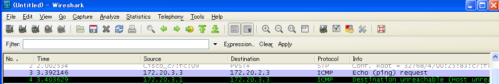
このような設定では、 VPC1 から VPC2 へ ping を打つと、返事が返って きません。これは何故でしょう?
C:\Documents and Settings\sakamoto>ping 172.20.12.3

Pinging 172.20.12.3 with 32 bytes of data:

Reply from 172.20.13.1: Destination host unreachable.
Reply from 172.20.13.1: Destination host unreachable.
Reply from 172.20.13.1: Destination host unreachable.
Reply from 172.20.13.1: Destination host unreachable.

Ping statistics for 172.20.12.3:
    Packets: Sent = 4, Received = 4, Lost = 0 (0% loss),
Approximate round trip times in milli-seconds:
    Minimum = 0ms, Maximum = 0ms, Average = 0ms

C:\Documents and Settings\sakamoto>
これは双方のルータにおいて、ネットワーク情報が不十分なため、不明なネッ トワークを相手のルータに託せるか判断ができないためです。 Wire Shark で確かめてみましょう。
するとスイッチ側のルータに届きます。 スイッチ側のルータのルーティングケーブルには次のエントリがあります。
catalyst3560#show ip route
Codes: C - connected, S - static, R - RIP, M - mobile, B - BGP
       D - EIGRP, EX - EIGRP external, O - OSPF, IA - OSPF inter area
       N1 - OSPF NSSA external type 1, N2 - OSPF NSSA external type 2
       E1 - OSPF external type 1, E2 - OSPF external type 2
       i - IS-IS, su - IS-IS summary, L1 - IS-IS level-1, L2 - IS-IS level-2
       ia - IS-IS inter area, * - candidate default, U - per-user static route
       o - ODR, P - periodic downloaded static route

Gateway of last resort is not set

     172.20.0.0/24 is subnetted, 2 subnets
C       172.20.13.0 is directly connected, Vlan14
C       172.20.15.0 is directly connected, FastEthernet0/6
catalyst3560#
このため、ルーティングテーブルに必要な情報を書き込む必要があります。
とりあえず、スイッチ側のルータのルーティングテーブルにスタテイックに情 報を書いてみます。
configure terminal
ip route 172.20.12.0 255.255.255.0 172.20.15.1
end
catalyst3560#show ip route
Codes: C - connected, S - static, R - RIP, M - mobile, B - BGP
       D - EIGRP, EX - EIGRP external, O - OSPF, IA - OSPF inter area
       N1 - OSPF NSSA external type 1, N2 - OSPF NSSA external type 2
       E1 - OSPF external type 1, E2 - OSPF external type 2
       i - IS-IS, su - IS-IS summary, L1 - IS-IS level-1, L2 - IS-IS level-2
       ia - IS-IS inter area, * - candidate default, U - per-user static route
       o - ODR, P - periodic downloaded static route

Gateway of last resort is not set

     172.20.0.0/24 is subnetted, 3 subnets
S       172.20.12.0 [1/0] via 172.20.15.1
C       172.20.13.0 is directly connected, Vlan14
C       172.20.15.0 is directly connected, FastEthernet0/6
このようにし、 VPC1 から
C:\Documents and Settings\sakamoto>ping 172.20.12.3

Pinging 172.20.12.3 with 32 bytes of data:

Request timed out.
Request timed out.
Request timed out.
Request timed out.

Ping statistics for 172.20.12.3:
    Packets: Sent = 4, Received = 0, Lost = 4 (100% loss),

C:\Documents and Settings\sakamoto>
するとスイッチ側のルータに届きます。 スイッチ側のルータのルーティングケーブルには次のエントリがあります。
     172.20.0.0/24 is subnetted, 3 subnets
S       172.20.12.0 [1/0] via 172.20.15.1
C       172.20.13.0 is directly connected, Vlan14
C       172.20.15.0 is directly connected, FastEthernet0/6
1841 ルータ のルーティングテーブルは次の様になっています。
    172.20.0.0/24 is subnetted, 2 subnets
C       172.20.12.0 is directly connected, FastEthernet0/1
C       172.20.15.0 is directly connected, FastEthernet0/0
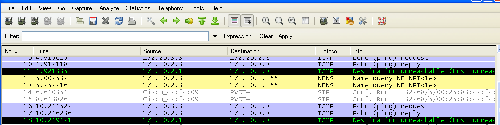
従って、 172.20.13.3 宛のパケットの転送先は計算できず、 VPC2 宛に ICMP Unreachable が 送られます。
VPC2 に ICMP Unreachable が届きますが、それ以上何も起きません。 そのため、 VPC1 は何もメッセージを受けとりません。
VPC1 はタイムアウトを表示します。
1841 ルータにスタティックルートを設定します。
configure terminal
ip route 172.20.13.0 255.255.255.0 172.20.15.2
end
すると、初めて VPC1 の
この時の各ルータのルーティングテーブルは次の様になっています。
     172.20.0.0/24 is subnetted, 3 subnets
C       172.20.12.0 is directly connected, FastEthernet0/1
S       172.20.13.0 [1/0] via 172.20.15.2
C       172.20.15.0 is directly connected, FastEthernet0/0
    172.20.0.0/24 is subnetted, 3 subnets
S       172.20.12.0 [1/0] via 172.20.15.1
C       172.20.13.0 is directly connected, Vlan14
C       172.20.15.0 is directly connected, FastEthernet0/6
S はスタティックルートを表しています。
次に、各ルータのスタティックルートを削除して、 RIP プロトコルでルーティ ングテーブルを計算させましょう。
configure terminal
no ip route 172.20.13.0 255.255.255.0

router rip
network 172.20.0.0
end
configure terminal
no ip route 172.20.12.0 255.255.255.0

router rip
network 172.20.0.0
end
このときのルーティングテーブルは次の様になっています。
     172.20.0.0/24 is subnetted, 3 subnets
C       172.20.12.0 is directly connected, FastEthernet0/1
R       172.20.13.0 [120/1] via 172.20.15.2, 00:00:19, FastEthernet0/0
C       172.20.15.0 is directly connected, FastEthernet0/0
     172.20.0.0/24 is subnetted, 3 subnets
R       172.20.12.0 [120/1] via 172.20.15.1, 00:00:05, FastEthernet0/6
C       172.20.13.0 is directly connected, Vlan14
C       172.20.15.0 is directly connected, FastEthernet0/6
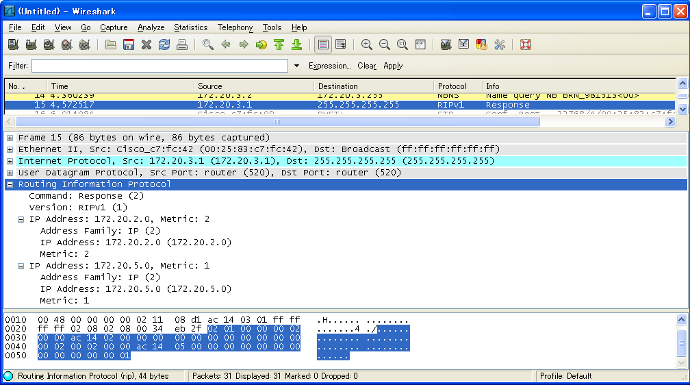
また、 Wire Shark で取得できる RIP のパケットは次の様になっています。
次に、RIP を止めて OSPF でルーティングテーブルを計算させましょう。
configure terminal
no router rip

router ospf 109
network 172.20.0.0 255.255.0.0 area 0
end
configure terminal
no router rip

router ospf 109
network 172.20.0.0 255.255.0.0 area 0
end
このときのルーティングテーブルは次の様になっています。
Codes: C - connected, S - static, R - RIP, M - mobile, B - BGP
       D - EIGRP, EX - EIGRP external, O - OSPF, IA - OSPF inter area
       N1 - OSPF NSSA external type 1, N2 - OSPF NSSA external type 2
       E1 - OSPF external type 1, E2 - OSPF external type 2
       i - IS-IS, su - IS-IS summary, L1 - IS-IS level-1, L2 - IS-IS level-2
       ia - IS-IS inter area, * - candidate default, U - per-user static route
       o - ODR, P - periodic downloaded static route

Gateway of last resort is not set

     172.20.0.0/24 is subnetted, 3 subnets
C       172.20.12.0 is directly connected, FastEthernet0/1
O       172.20.13.0 [110/2] via 172.20.15.2, 00:14:41, FastEthernet0/0
C       172.20.15.0 is directly connected, FastEthernet0/0
Codes: C - connected, S - static, R - RIP, M - mobile, B - BGP
       D - EIGRP, EX - EIGRP external, O - OSPF, IA - OSPF inter area
       N1 - OSPF NSSA external type 1, N2 - OSPF NSSA external type 2
       E1 - OSPF external type 1, E2 - OSPF external type 2
       i - IS-IS, su - IS-IS summary, L1 - IS-IS level-1, L2 - IS-IS level-2
       ia - IS-IS inter area, * - candidate default, U - per-user static route
       o - ODR, P - periodic downloaded static route

Gateway of last resort is not set

     172.20.0.0/24 is subnetted, 3 subnets
O       172.20.12.0 [110/2] via 172.20.15.1, 00:13:20, FastEthernet0/6
C       172.20.13.0 is directly connected, Vlan14
C       172.20.15.0 is directly connected, FastEthernet0/6
また、 Wire Shark で取得できる OSPF のパケットは次の様になっています。
ルータが2台以上あると、相互に独立に接続しているネットワークの情報を知 らなければなりません。 手動で行うのはスタティックルーティングで、これは各情報をじかに入力する ものです。 一方ダイナミックルーティングとして RIP や OSPF があります。 これらは、原理が大きく異なりますが、設定方法はかなり似ています。 但し、RIP はサブネットマスクを伝搬しませんので、その設定もありません。
また、 ping に関して、行きの経路が無い場合は ICMP unreachable を受ける ためエラーを検知できますが、帰りの経路が無い場合はエラーを受けることが できずタイムアウトします。
東京電機大学キャンパスネットワークは2018年度に増強が行われました。 バックボーンが10Gbit Ethernet となり、無線LANが増強されました。